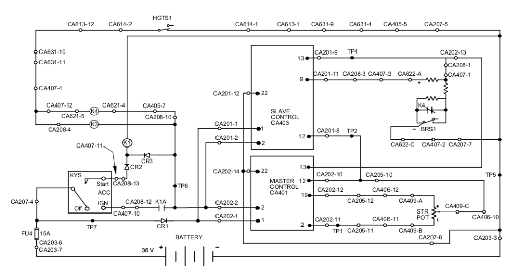
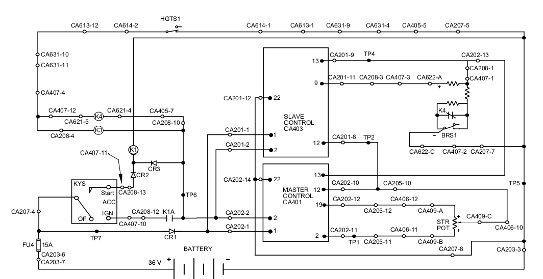
Brake Switch (BRS1) depressed for more than 5 seconds while requesting traction. –04
This code indicates voltage at CA401-13 on master controller (MRC1) and CA403-13 on slave controller (MRC2) is 2.6 volts and traction has been commanded for 5 seconds.
Step 1: Release parking brake.
If code still exists after 5 seconds of traction.
Then proceed to step 2.
Step 2: Verify adjustment of brake switch BRS1 and accelerator switch ACS. Refer to section M4.0 of the service manual for adjustment instructions.
Step 3: Check voltage at TP4 on the distribution panel for 1.3 volts while parking brake and service brake pedal are released and 2.6 volts while service brake pedal is depressed.
If voltages as described.
Then proceed to step 4.
If voltages not as described.
Then adjust or replace BRS1 as necessary.
Then locate and repair loose connection or wiring between Brake Pot Module and BRS1.
Then locate and repair loose connection or wiring between CA208-1 on the distribution panel and Brake
Pot Module.
Then calibrate Brake Pot Module. Refer to section M4.3 of the service manual for calibration instructions.
Then replace Brake Pot Module.
Step 4: Check voltage at CA401-13 on master controller or CA403-13 on slave controller for 1.3 volts while parking brake and service brake pedal are released and 2.6 volts while service brake pedal is depressed.
If voltages as described.
Then proceed to step 5.
If voltages not as described.
Then locate and repair loose connection or wiring between CA202-13 on distribution panel and CA401-13 on master controller or between CA201-9 on the distribution panel and CA403-13 on slave controller.
Step 5: Check voltage with voltmeter positive probe at CA403-9 on slave controller with Brake Pot Module unplugged from main wire harness at CA622.
If 4.3 volts.
Then replace appropriate controller. See note.
If greater than 4.3 Volts.
Then locate and repair loose connection or wiring between CA403-9, CA403-13 and Brake Pot Module.
Then check mounting and calibration of Brake Pot Module.
Then replace Brake Pot Module.
Then replace slave controller. See note.
If less than 0.3 volts.
Then check all wiring between CA403-9, CA403-13 and Brake Pot Module for loose or open connections.
Then check mounting and calibration of Brake Pot Module.
Then replace slave controller. See note.
Note: If brake potentiometer wiper voltage input at CA401-13 on master controller and CA403-13 on slave controller is 1.3 volts while parking brake and service brake pedal are released and mast collapsed and 2.6 volts while service brake pedal is depressed and mast collapsed and the Brake Pot Module is powered from CA403-8 and CA403-9 and event code –04 is still displayed, then and only then, replace the appropriate controller. RS232 communication between master controller and slave controller must be disabled to determine the appropriate controller. Refer to the steps located at the beginning of this event code section to disable RS232 communication. Replace only the controller with an event code –04 stored. Adjust all function codes as necessary. If Brake Pot Module power supply from CA403-9 is greater than 4.3 volts, replace slave controller.


