
Encoder Operation and Testing
Encoders are used for many different functions during lift truck operation. The basic principle of the encoder is to convert mechanical motion into a digital signal. This digital signal is used to sense direction of a component as well as speed. Most encoders have 4 wires, some have 5.
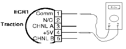
Wire Designations
- Supply wire: Used to provide positive voltage input to the encoder, can be 5v, 11.3v or 12v.
- Common wire: Used to provide negative input to the encoder.
- Channel wire A: Used to provide output signal from encoder to module. When signal is present on channel A there is a slight overlap before a signal is not present on channel B.
- Channel B wire: Used to provide output signal from encoder to module. When signal is present on channel B there is a slight overlap before a signal is not present on channel A.
- Index wire: Not present on all encoders, used to provide a “center” reference point in applications such as steering feedback.

Basic electrical troubleshooting of an encoder using a Digital Volt Meter can easily determine if an encoder has failed
- Supply Test: 5 volt encoder should have 5v supply between common wire and supply.
- Channel A Feedback Test: The encoder sends pulses of 5v supply out of the channel wires. Digital volt meters are not responsive enough to pick up the exact pulse signal. The meter will show an average voltage when the encoder is turning, on a 5 volt encoder the correct voltage is 2.5 volts. A voltage that varies from the 2.5 average, indicates a faulty encoder.

Expected Encoder Feedback Voltages
5 volt encoder = 2.5 volts when turning
11.3 volt encoder= 5.5 volts when turning
12 volt encoder= 6.0 volts when turning
- Channel B Feedback Test: The encoder sends pulses of 5v supply out of the channel wires. Digital volt meters are not responsive enough to pick up the exact pulse signal. The meter will show an average voltage when the encoder is turning, on a 5 volt encoder the correct voltage is 2.5 volts. A voltage that varies from the 2.5 average, indicates a faulty encoder.

- Index Test: Some encoders such as those that are used for steering feedback and lift command have a 5th wire that is called index. Index is used to provide a signal to indicate a center position. When the encoder is turned to the index position only, a 5 volt signal will be present on the index wire.
