

Key switch to “ON” position
Control card energizes regenerative braking diver (Wire 32), regenerative braking contactor closes. Battery volts at TB-4 (Wire 10). Battery volts at seat switch.
Seat switch closed
Voltage to TB-3 through timer/filter block. Control card energizes accelerator circuit and terminal 1 of PMT driver. Brake switch must also be closed if so equipped.
TB-2 Search
Low voltage signal to direction switches to check for a closed direction switch. (Shorted, mis-adjusted, or column lever left in a direction).
Operator selects direction and steps on accelerator pedal
Accelerator start switch closes and supplies voltage to contactor coil. (Card must sense voltage at TB-3 and TB-4 BEFORE voltage at either TB-5 or TB-6).
PMT Initial Search
Card checks for approximately 50% of battery volts ACROSS #1 SCR. PMT signal removed if voltage not present. If either SRO or PMT checks are not satisfied, voltage on wire 24 to PMT driver is removed.
SRO and PMT satisfied
Control set to “FORWARD”, forward contactor closes.
Control card sends gate signal to SCR 2 to complete negative path to C1. C1 charges to battery volts. SCR 2 goes “OFF” because no current flow. Control card senses charge on C1 through ORANGE wire.
Control card sends gate signal to SCR 1 and SCR 5. Power pulse to traction circuit.
SCR 5 goes “OFF”. C1 charged with reverse polarity.
Control card sends gate signal to SCR 2. SCR 2 goes “ON”. C1 discharges to SCR 1 cathode.
SCR 1 is “BLOCKED OFF”. Control card repeats cycle PMT circuit constantly monitors “ON TIME” of SCR 1.
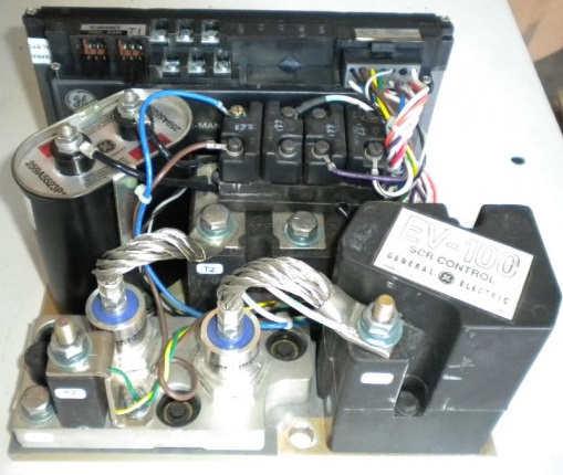
SCR’s (1REC, 2REC, 5REC)
These are silicon controlled rectifiers. Before checking, disconnect the battery and discharge capacitor 1C. Disconnect gate leads from SCR’s at the SCR terminal.
To check an SCR it is necessary to have a 6V Battery and 2 A-14 Diodes.
Connect the positive lead to the anode, connect the negative lead to the cathode.

- The lamp should not light. If the lamp does light, the SCR is shorted and must be replaced.
- If check 1 was satisfactory, test the SCR for its ability to be turned on by the gate. Connect positive through two diodes to the gate terminal. If the gate is operative, the lamp will come on and remain on when the gate is removed. Some SCR’s will operate correctly even if the lamp does not remain on, particularly with a weak battery.
- If the lamp cannot be lit under step 2, the SCR is open and must be replaced.