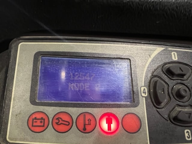
Identifiers to determine which device generated the code:
Node X = XXXX (12544 Node 3)
Node 2 = Traction
Node 5 = Pump
Node 6 = Steer Master
Node 7 = CAN I/O Master
Node 8 = CAN I/O Slave
Node 11 = Forward Antenna
Node 12 = Reverse Antenna
Node 16 = Display
| 4096 Node 2 | Drive wheel angle is not valid. |
| 4097 Node 2 | The traction controller has detected an alarm in the CAN I/O |
| 4128 Node 6 | Steer motor controller (EPS) determines there is an alarm condition in the forward or reverse antenna. |
| 4129 Node 6 | Drive wheel does not center within six seconds. |
| 4130 Node 6 | Steer (EPS) controller detects CAN I/O has an error. |
| 8480 Node 6 | When in wire guidance mode, one or both antennas are not sensing the magnetic field from the wire. |
| 8481 Node 6 | When in wire guidance mode, the truck has moved too far laterally from the wire. |
| 8482 Node 6 | When in wire guidance mode, steer wheel angle is outside the limiting threshold Node 6 between truck angle and wire. |
| 8961 Node 2 | The traction controller has noted an incorrect output voltage for the proportional valve control. |
| 8962 Node 2 | The traction controller has noted an incorrect output voltage for the load hold valve Node 2 control. |
| 8963 Node 3 | Overcurrent detected from outputs on traction controller connector CPS100 pins 8, 11, and 33. |
| 8964 Node 2 | The RELAY1 coil driver is shorted or RELAY1 coil open. |
| 8965 Node 2 | The Pump contactor driver is shorted or the HYD PUMP COIL circuit is open. |
| 8966 Node 2 | The back-up alarm driver shorted or open load circuit. |
| 8967 Node 2 | Main contactor output driver shorted to battery negative (B-) or open main contactor coil circuit detected. |
| 8968 Node 2 | No positive supply to electric brake. |
| 8969 Node 2 | The high side driver of the parking brake coil is shorted (24V system only). |
| 8970 Node 2 | Low side driver of the electric brake is shorted or open brake coil. |
| 8971 Node 2 | One of the traction motor phases has an open circuit. |
| 8972 Node 2 | The main line contactor coil or the parking brake coil has detected an overcurrent condition. |
| 8973 Node 2 | The lift /lower proportional valve coil circuit is open or shorted. |
| 8974 Node 2 | The load hold valve coil circuit is open. |
| 8992 Node 6 | Steer (EPS) power failure motor phase W or problems with steer speed encoder. |
| 8993 Node 6 | Steer (EPS) power failure motor phase V or problems with steer speed encoder. |
| 8994 Node 6 | Steer (EPS) power failure motor phase U or problems with steer speed encoder. |
| 8996 Node 6 | Steer (EPS) motor in a locked rotor condition. |
| 12289 Node 2 | Traction throttle voltage is out of range. |
| 12290 Node 2 | Lift throttle voltage is out of range (R30XM3/XMA3/XMF3 only). |
| 12291 Node 2 | A traction motor speed encoder fault has been detected. |
| 12292 Node 2 | A traction motor stall condition has been detected. |
| 12293 Node 2 | Lift and lower commands are being requested simultaneously (R30XMS3 only). |
| 12321 Node 6 | Steer (EPS) motor power phases output mismatch between EPS slave and EPS master. |
| 12322 Node 6 | Steer motor encoder mismatch between steer (EPS) master controller and steer (EPS) slave controller microprocessor. |
| 12323 Node 6 | Steer EPS controller has detected a position mismatch between the centering prox Node 6 switch and the steer motor encoder. |
| 12324 Node 6 | EPS motor encoder error between commanded and actual frequency. |
| 12325 Node 6 | Command and encoder feedback direction not matched. |
| 12352 Node 7 & 8 | Auto center steer sensor inputs out of range. |
| 12544 Node 2 | The battery voltage has been detected as too high or too low. |
| 12545 Node 2 | Pin 3 of the traction controller connector is not connected to battery positive or there is a difference between the voltage at pin 3 and the voltage at pin 10, the controller key switch input voltage (24V truck only). |
| 12546 Node 2 | Pin 3 of the traction controller connector is not connected to the battery positive or there is a difference between the voltage at pin 3 and the voltage ay pin 10, the controller key switch input (36V truck only). |
| 12547 Node 2 | A traction controller under voltage or over voltage condition has been detected. |
| 12548 Node 2 | Traction controller DC bus capacitor voltage is too low or capacitor pre-charge is Node 2 not complete. |
| 12549 Node 2 | The main line contactor has been detected as closed. |
| 12550 Node 2 | The main line contactor remains open after power is applied to the coil. |
| 12554 Node 5 | Hoist Controller detects incorrect battery voltage. |
| 12705 Node 5 | The voltage between the B+ and B- of the ACE2 hoist controller has been detected too low. |
| 12706 Node 5 | Hoist controller is not receiving CAN messages from ACE0 traction controller. |
| 13056 Node 2 | The traction motor voltage is lower than expected at initial start-up. |
| 13057 Node 2 | The traction motor voltage is higher than expected at initial start-up. |
| 13058 Node 2 | The traction controller has detected an alarm condition in the steer controller. |
| 13059 Node 2 | The traction controller detects STEER STATUS is ON at key on. |
| 13088 Node 6 | Wrong voltage on steer security line. |
| 13089 Node 6 | EPS connector CPS120 pin 5 not receiving battery voltage from key switch. |
| 13216 Node 5 | Hoist controller internal failure, harness issue or shorted power connections to the hoist motor. |
| 13217 Node 5 | Hoist controller capacitor charging circuit failure. |
| 13218 Node 5 | Hoist controller over or under voltage detected |
| 13219 Node 5 | AC hoist motor encoder error. |
| 20480 Node 2 | Traction controller has indicated an internal failure of the controller. |
| 20512 Node 6 | The steer controller has indicated an internal failure of the controller. |
| 20544 Node 7 & 8 | Multiturn steering or internal controller failure. |
| 20576 Node 11 | Antenna forward – Internal failure |
| 20608 Node 11 | Antenna reverse – Internal failure |
| 20640 Node 5 | Hoist controller – Internal failure |
| 20672 Node 16 | Display – Internal failure |
| 25345 Node 2 | The performance mode parameter values have been entered incorrectly. |
| 25346 Node 2 | The height versus traction speed map parameters have been entered incorrectly. |
| 25347 Node 2 | The slip map parameters are set incorrectly. |
| 25348 Node 2 | The traction controller configuration voltage is set incorrectly. |
| 25349 Node 2 | There is a mismatch condition with the traction motor speed encoder pulses per revolution. |
| 25350 Node 2 | There is a mismatch condition between the mast prox switch and the height encoder. |
| 25351 Node 2 | No height encoder counts detected when platform is lifting or lowering. |
| 25376 Node 6 | Parameter mismatch between CAN I/O and EPS controller. |
| 25408 Node 7 & 8 | Stepper motor signals shorted to B-. |
| 25409 Node 7 & 8 | Stepper motor Q signal (wire 400) not connected. |
| 25410 Node 7 & 8 | Stepper motor D signal (wire 401) not connected |
| 33024 Node 2 | The traction controller has noted no CAN communication with the CAN I/O master microprocessor. |
| 33025 Node 2 | The traction controller has noted no CAN communication with the CAN I/O slave Node 2 microprocessor. |
| 33026 Node 2 | The traction controller has noted no CAN communication with the steer controller. |
| 33027 Node 2 | The traction controller has noted no CAN communication with the hoist controller. |
| 33028 Node 2 | The traction controller has noted no CAN communication with the display. |
| 33056 Node 6 | The forward antenna is not present on the CAN. |
| 33057 Node 6 | The reverse antenna is not present on the CAN. |
| 33059 Node 6 | No communication with the CAN I/O slave. |
| 33060 Node 6 | Steer controller EPS has lost CANbus communication with the traction controller. |
| 33061 Node 6 | Steer controller (EPS) master microprocessor has lost CANbus communication with the CAN I/O. |
| 33088 Node 7 & 8 | No communication from CAN I/O slave microprocessor to CAN I/O master. |
| 33089 Node 7 & 8 | No communication from traction controller to CAN I/O master. |
| 33090 Node 7 & 8 | No communication from CAN I/O master to CAN I/O slave. |
| 33091 Node 7 & 8 | No communication from traction controller to CAN I/O slave. |
| 33216 Node 16 | Display has a CANbus communication error with the traction controller. |
| 33217 Node 16 | Display has a CANbus communication error with the steer controller. |
| 33218 Node 16 | Display has a CANbus communication error with the pump controller. |
| 33219 Node 16 | Display has a CANbus communication error with the CAN I/O controller (master). |
| 33220 Node 16 | Display has a CANbus communication error with the CAN I/O controller (slave). |

