
This code is set when the fingertip hydraulic levers are out of range when the key is turned on. Moving each lever back and forth will usually clear the code until the key is cycled again. To reset the code permanently, you will need a code to get into the dash. Press the star symbol three times and it should read enter password on the display. Try the local zip codes where the unit was purchased.
CODES
DTC 523261-12 – Lever 1 Position Data Invalid
DTC 523257-12 – Lever 2 Position Data Invalid
DTC 523253-12 – Lever 3 Position Data Invalid
DTC 523249-12 – Lever 4 Position Data Invalid
POSSIBLE CAUSE
A. LEVER/PCB CASSETTE MECHANISM WORN OR STUCK
B. MLM PCB CASSETTE ELECTRICAL FAILURE
COMPONENT OPERATIONAL CHECK
PROCEDURE OR ACTION:
- Turn power to OFF for no less than 30 seconds, and then to ON to clear displayed DTC.
Does reported DTC reoccur?
YES: Go to Step 3.
NO: Problem not verified. Resume operation. - Conduct a thorough visual inspection of all seat connectors/wiring.
Are any faults detected/observed?
YES: Repair/replace connector or wiring associated with faults found. See Electrical System 2200SRM1142.
NO: Go to CAUSE A.
CAUSE A – LEVER/PCB CASSETTE MECHANISM WORN OR STUCK
PROCEDURE OR ACTION:
- Turn power to OFF.
- Move Indicated Lever(s) to the full stroke position and slowly return to the center position. Repeat in the
opposite direction.
Does the Lever action appear to be smooth (without friction), and does the lever return to the center
position?
YES: Go to Step 3.
NO: Go to Step 4. - Perform E–Hydraulic Controls – Test. See Electrical System 2200SRM1142.
Do the Levers perform within the specified operational range?
YES: Go to CAUSE B.
NO: Replace Faulty Lever with one that has the same part number and Retest. - Remove lever, and with Lever Base held securely move lever to the full stroke position and slowly return to
the center position. Repeat in the opposite direction.
Does the Lever action appear to be smooth (without friction), and does the lever return to the center
position?
YES: Go to CAUSE B.
NO: Replace Faulty Lever with one that has the same part number and Retest.
CAUSE B – MLM PCB CASSETTE ELECTRICAL FAILURE
PROCEDURE OR ACTION:
- MLM PCB Cassette. See Electrical System 2200SRM1142.
- Perform E Hydraulic Controls – TEST. See Electrical System 2200SRM1142.
Do the Lever(s) perform within the specified operational range?
YES: Problem corrected. Resume operation.
NO: Repeat steps starting at CAUSE A.

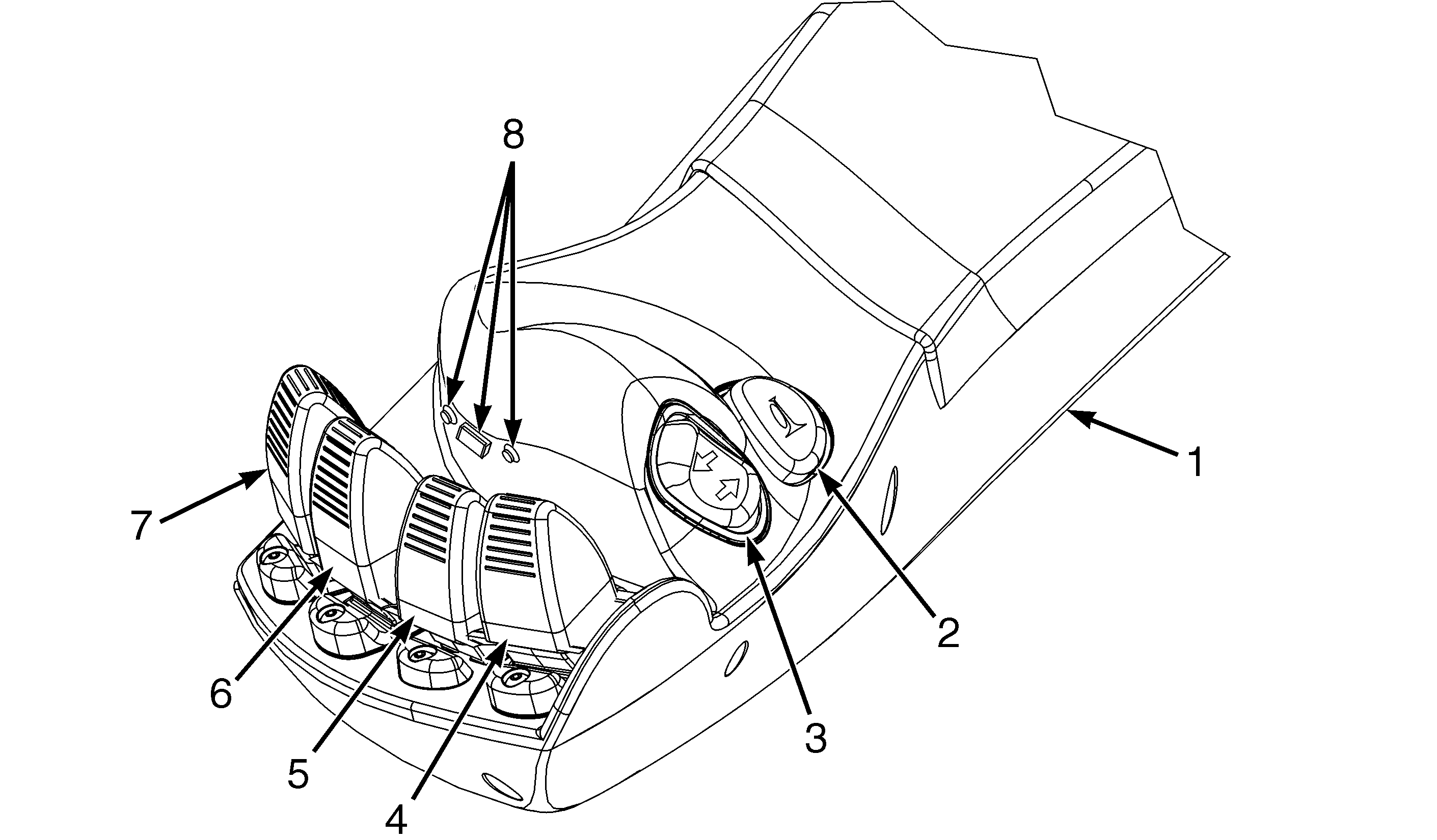
- ARM REST
- HORN BUTTON
- DIRECTIONAL SWITCH
- LIFT/LOWER CONTROL LEVER
- TILT CONTROL LEVER
- AUXILIARY HYDRAULIC FUNCTIONS (3RD
LEVER) - AUXILIARY HYDRAULIC FUNCTIONS (4TH
LEVER) - SWITCH – MOMENTARY